
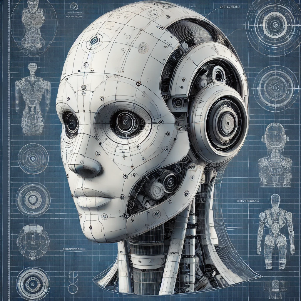
A humanoid robot head is a highly complex component that combines functionality, aesthetics, and interaction capabilities. The head serves as the central point for communication, sensory input, and computational processes. Below is a comprehensive guide to designing a humanoid robot head.
1. Functional Objectives
The humanoid robot head must:
- House Sensory Systems: Cameras, microphones, LiDAR, and other sensors.
- Enable Interaction: Include features for speech, facial expressions, and visual communication.
- Support Processing Units: Contain processors for sensory data and decision-making.
- Facilitate Movement: Include neck joints for rotation, tilting, and nodding.
- Ensure Aesthetic Appeal: Mimic human-like features for relatable interaction.
2. Key Components of a Robotic Head
| Component | Function |
| Camera Modules | Vision for object detection, recognition, and tracking. |
| Microphones | Capture audio for speech recognition and environmental sounds. |
| Speakers | Output for speech synthesis and sound effects. |
| Display Panel | Visual communication via screen (e.g., eyes, status indicators). |
| Actuators | Drive facial expressions and head movements. |
| Frame Structure | Provide support and shape for the head. |
| Cooling Systems | Manage heat from processors and electronics. |
| Sensors | Include tactile, proximity, temperature, and IMU sensors for interactions. |
| Neck Joints | Enable head movements like rotation, tilt, and nodding. |
3. Design Process
Step 1: Define Functional Capabilities
- Vision: Incorporate stereo cameras for depth perception or a LiDAR system for environmental mapping.
- Hearing: Use multi-directional microphones for noise-canceling and directional audio input.
- Expression: Add motorized mechanisms for eyebrow, eyelid, and lip movements.
Step 2: Structural Design
- Use CAD software (e.g., SolidWorks, Fusion 360) to create a 3D model of the head.
- Design compartments for sensors, actuators, and processors.
- Select materials like lightweight ABS plastic or carbon fiber for the shell.
Step 3: Sensor Integration
- Vision System:
- Use dual RGB cameras for stereoscopic vision.
- Add infrared cameras for low-light environments.
- Audio System:
- Position microphones strategically for accurate sound localization.
- Proximity Sensors:
- Place sensors to detect objects close to the head.
Step 4: Mobility
- Design neck joints with servos or actuators for movements:
- Yaw: Side-to-side rotation.
- Pitch: Up and down tilt.
- Roll: Side tilting for expressive gestures.
- Incorporate IMU sensors for balance and orientation tracking.
Step 5: Communication Features
- Add a speaker for speech synthesis.
- Include a small display for visual expressions like animated eyes or text communication.
Step 6: Aesthetics
- Create human-like features (e.g., skin texture, symmetrical face).
- Consider customizable appearances for different use cases.
4. Key Subsystems
4.1 Vision Subsystem
| Component | Description | Example |
| Stereo Camera | Provides depth perception for 3D vision. | RGB-D Camera, Intel RealSense D415 |
| Infrared Camera | Captures images in low-light environments. | FLIR Lepton |
| LiDAR Sensor | Maps the surroundings for obstacle detection. | Hokuyo UTM-30LX |
4.2 Audio Subsystem
| Component | Description | Example |
| Microphone Array | Multi-directional microphones for clear audio capture. | ReSpeaker Mic Array |
| Speaker | Outputs synthesized speech and sound effects. | HiFi Mini Speaker |
4.3 Actuation Subsystem
| Component | Description | Example |
| Servo Motors | Control head movements and facial expressions. | MG996R Servo Motor |
| Linear Actuators | Drive specific facial gestures like blinking or smiling. | Firgelli Mini Linear Actuator |
4.4 Processing Subsystem
| Component | Description | Example |
| AI Processor | Handles vision, speech recognition, and decision-making. | NVIDIA Jetson Nano, Raspberry Pi 4 |
| Feedback Controller | Ensures smooth operation of actuators based on sensor inputs. | Arduino Mega, STM32 Microcontroller |
5. Material Selection
- Outer Shell: ABS plastic for durability and lightweight construction.
- Internal Frame: Aluminum or carbon fiber for strength and weight reduction.
6. Cooling System
- Active Cooling: Use small fans or heat sinks for processors and actuators.
- Passive Cooling: Design ventilation slots for natural heat dissipation.
7. Control System
- Implement a centralized control unit to process inputs and outputs from all sensors and actuators.
- Use Robot Operating System (ROS) for modular software architecture.
8. Challenges and Solutions
| Challenge | Solution |
| Limited Space | Optimize internal design with compact components. |
| Overheating | Use efficient cooling systems and low-power processors. |
| Smooth Motion Control | Integrate PID controllers for actuators. |
| Realistic Expressions | Use high-precision servos for fine control of facial features. |
| Lightweight Design | Select lightweight materials like ABS and carbon fiber. |
9. Advanced Features
- Facial Recognition: Use AI for identifying and interacting with individuals.
- Dynamic Expressions: Implement complex facial gestures for realistic communication.
- Voice Synthesis: Integrate text-to-speech systems for natural conversations.
10. Tools and Software
- Design Software: SolidWorks, Fusion 360 for mechanical design.
- Simulation Tools: Gazebo, MATLAB/Simulink for motion and sensor testing.
- Programming Frameworks: Python, C++ with ROS for system integration.
Conclusion
Designing a humanoid robot head requires a balance between functionality, aesthetics, and computational power. By integrating advanced sensory systems, robust structural design, and adaptive control, a humanoid head can effectively interact with its environment and users, serving various applications from social robots to industrial assistants.