
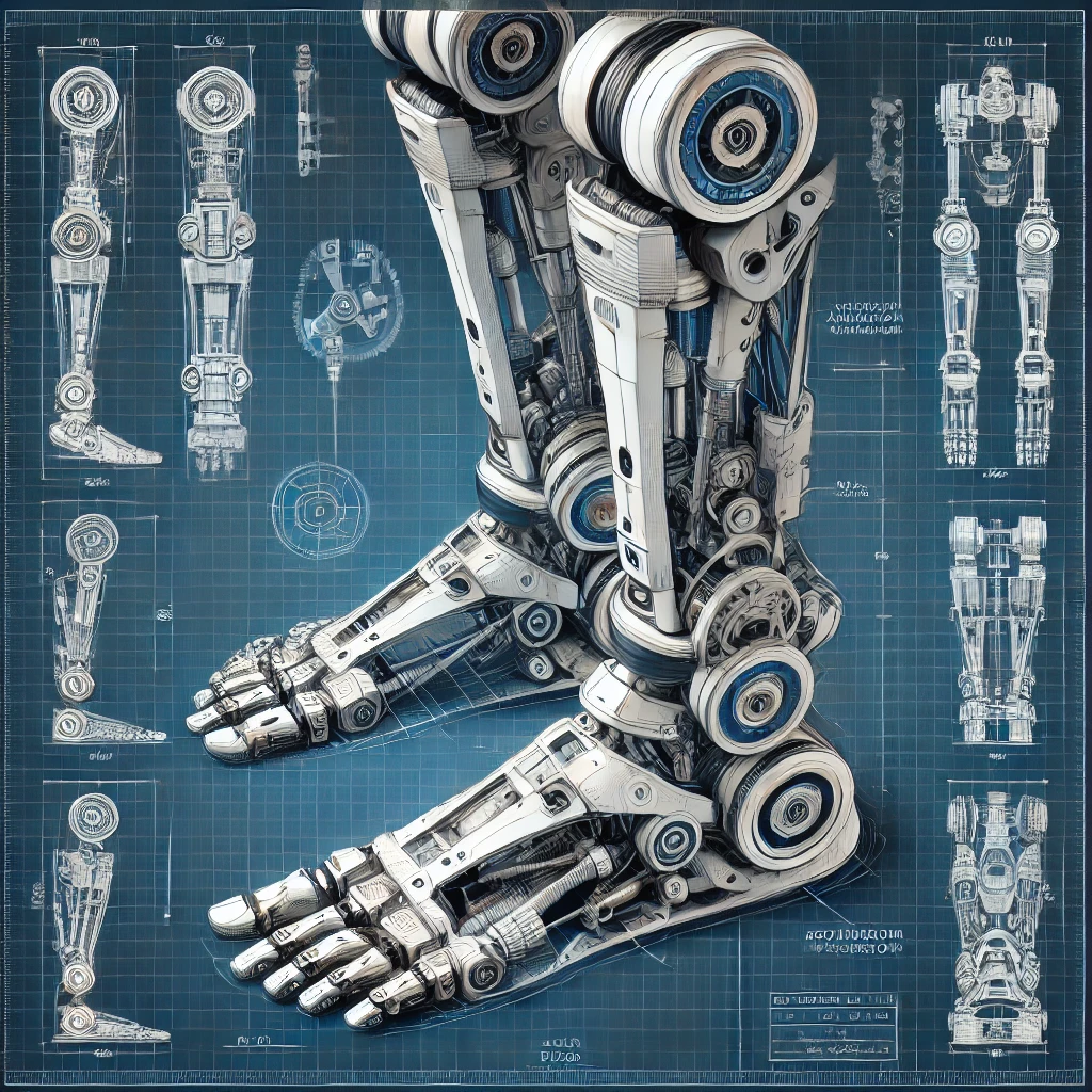
The leg, ankle, and foot are essential for a humanoid robot’s mobility, balance, and interaction with the environment. They must provide the necessary range of motion, load-bearing capacity, and dynamic stability to support various tasks such as walking, running, climbing stairs, and maintaining balance.
1. Functional Objectives
The robotic leg, ankle, and foot must:
- Support Weight: Bear the robot’s weight and maintain structural stability.
- Enable Motion: Provide a range of movements to mimic human locomotion.
- Maintain Balance: Adapt dynamically to uneven terrain and external forces.
- Ensure Durability: Withstand repetitive loads and environmental conditions.
- Provide Feedback: Use sensors to detect pressure, position, and orientation for real-time adjustments.
2. Key Components
| Component | Function |
| Leg Frame | Provides structural support and connects the hip to the ankle. |
| Joints | Allow movement at the knee and ankle. |
| Actuators | Drive motion at the knee, ankle, and foot. |
| Sensors | Monitor position, torque, pressure, and orientation. |
| Foot Plate | Distributes pressure and interacts with the ground. |
| Shock Absorbers | Reduce impact forces during walking or running. |
| Control System | Coordinates movement and adjusts dynamically based on feedback. |
| Power Transmission | Transmits energy efficiently to actuators and joints. |
3. Designing the Leg
3.1 Structural Design
- Frame Material: Use lightweight materials like aluminum or carbon fiber.
- Load Distribution: Design the frame to evenly distribute weight between the hip and ankle.
3.2 Actuation
- Knee Joint: Provide forward and backward motion (pitch) using:
- Servo motors or BLDC motors for precision.
- Linear actuators for smooth flexion/extension.
- Sensors:
- Encoders: Measure joint angle and motion speed.
- Torque Sensors: Monitor forces at the knee joint.
4. Designing the Ankle
4.1 Degrees of Freedom (DOF)
- Pitch: Forward and backward tilting (~±30°).
- Roll: Side-to-side tilting (~±20°).
- Yaw (Optional): Twisting (~±15° for advanced designs).
4.2 Joint Mechanism
- Use rotary bearings and hinges for smooth multi-axis movement.
- Include harmonic drives for precise motion control.
4.3 Actuators
- Servo Motors: Provide fine control for balancing and motion.
- Linear Actuators: Enable vertical compression for shock absorption.
4.4 Sensors
- IMU (Inertial Measurement Unit): Tracks orientation and angular velocity.
- Force/Torque Sensors: Detect loads on the ankle joint.
- Pressure Sensors: Monitor ground reaction forces.
4.5 Integration with Control System
- Use real-time feedback from sensors for precise ankle adjustments.
- Implement adaptive algorithms for dynamic terrain handling.
5. Designing the Foot
5.1 Structural Design
- Shape and Size: Mimic human foot dimensions for natural gait and stability.
- Material: Use lightweight, durable materials like ABS plastic for the shell and rubber for traction pads.
5.2 Functional Features
- Foot Plate: Distributes load and interacts with the ground.
- Shock Absorbers: Reduce impact forces during ground contact.
- Tactile Sensors: Detect surface textures and pressure distribution.
5.3 Sensors
- Pressure Sensors:
- Detect weight distribution across the foot.
- Provide data for dynamic balance adjustments.
- Proximity Sensors: Identify obstacles near the foot.
5.4 Advanced Features
- Toe Articulation: Add actuators for independent toe movement to improve grip and walking efficiency.
- Heating Module: Maintain operational temperature in cold environments.
6. Power and Control Systems
- Central Processor: Use microcontrollers (e.g., STM32, Raspberry Pi) to manage real-time movements.
- Power Distribution: Include a power bus for actuators and sensors in the leg, ankle, and foot.
- Control Software: Implement algorithms for gait generation, balance, and terrain adaptation using ROS or similar frameworks.
7. Integration
- Leg to Hip: Use modular connectors to attach the leg securely to the hip joint.
- Ankle to Foot: Design flexible joints to transfer movement efficiently to the foot.
- Cabling: Use shielded wires to connect sensors and actuators without interference.
8. Example Subsystems
8.1 Leg Components
| Component | Description | Example |
| Upper Leg Frame | Connects the hip to the knee, supports load. | Aluminum Frame |
| Knee Actuator | Drives the knee joint for flexion/extension. | Firgelli Linear Actuator |
| IMU Sensor | Tracks orientation and angular velocity of the leg. | MPU-6050 |
8.2 Ankle Components
| Component | Description | Example |
| Rotary Actuator | Provides ankle tilt and rotation. | Maxon EC90 Flat Motor |
| Torque Sensor | Measures load on the ankle joint. | ATI Mini45 |
| Harmonic Drive | Enables precise rotational movement. | HD-14-2UH Harmonic Drive |
8.3 Foot Components
| Component | Description | Example |
| Foot Frame | Distributes pressure evenly across the surface. | Carbon Fiber Plate |
| Pressure Sensors | Detect weight distribution and ground forces. | Tekscan FlexiForce |
| Shock Absorber | Reduces impact forces during walking or running. | Polyurethane Dampers |
9. Advanced Features
- Dynamic Balance Control: Use AI to adjust leg, ankle, and foot movements for stability on uneven terrain.
- Energy Recovery: Implement regenerative braking in actuators to capture energy during motion deceleration.
- Dynamic Gait Adjustment: Integrate algorithms for real-time terrain analysis and adaptive walking.
10. Challenges and Solutions
| Challenge | Solution |
| High Impact Forces | Use shock absorbers and flexible foot materials. |
| Complex Multi-Axis Control | Employ high-precision sensors and advanced control algorithms. |
| Power Efficiency | Use lightweight materials and energy-efficient actuators. |
| Heat Dissipation | Include passive cooling (heat sinks) and active cooling (fans). |
11. Tools and Software
- Design Tools: SolidWorks, Fusion 360 for mechanical design.
- Simulation Tools: MATLAB/Simulink, Gazebo for testing gait and balance.
- Programming Frameworks: Python, C++ with ROS for system integration.
Conclusion
The leg, ankle, and foot of a humanoid robot are integral to its mobility and functionality. By combining advanced materials, precise actuators, real-time sensors, and adaptive control systems, a humanoid robot can achieve lifelike movement and stability across various terrains.